There has been some contention around the new earthing requirements in AS/NZS 5033:2021. The relevant clauses are 4.6.5 and Table 4.6. What do these new requirements actually mean? What the hell is a powered neutral? How does it change the way I install? Read on and we’ll break it down.
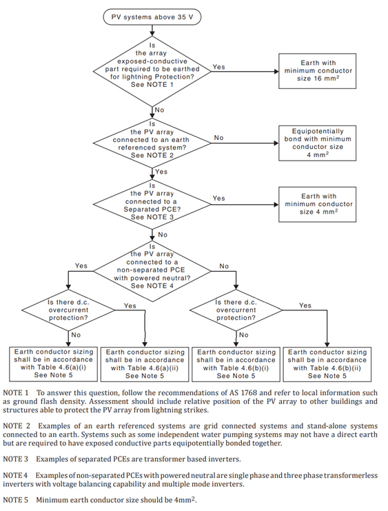
Lets start with the decision tree in 4.6.5
First up, does the array require lightning protection?
There is no change to this requirement compared to 5033:2014. You need to refer to AS 1768 in order to calculate the requirements for lightning protection.
Is the PV array connected to an earth referenced system?
ALL grid connected PV systems are earth referenced. Any inverter with an earth connection means the system is earth referenced. I do hope everyone is connecting the earth to their grid connected PV inverters…….
Is the PV array connected to a separated PCE? and Is the PV array connected to a non-separated PCE with powered neutral?
A separated PCE is an inverter that is galvanically isolated i.e. it has a physical transformer inside the inverter. There are almost no PV inverters available nowadays that are not transformer-less. Some of the more seasoned installers may remember installing galvanically isolated inverters and no doubt recall how heavy they were given the big coils inside of them. It is safe to assume that all the inverters anyone is installing today are non-separated (transformer-less).
But what is a powered neutral? Essentially what they mean here is, Does the neutral carry current? In the case of any single phase inverter the answer is yes, there will be current on the neutral. In the case of most three phase grid connected inverters the answer is no. A three phase inverter outputs a balanced supply on all three phases and do not put current on the neutral conductor. The exception to this would be if the three phase inverter is a hybrid capable of doing back-up. When in back-up mode the inverter would not only be supplying three phase balanced loads and thus current would be flowing in the neutral conductor to the inverter.
Is there D.C overcurrent protection?
This is basically string protection. Installers who regularly install commercial systems will be familiar with this while resi only guys may not be. It is where a DC fuse is installed on both positive (+) and negative (-) of every string. Given other changes in 5033:2021 this will almost always look like a DIN rail enclosure mounted next to the inverter with DIN mounted fuse holders inside of it.
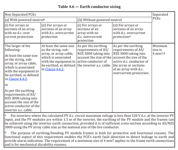
Now we’ve followed the decision tree, next we need to looks at Table 4.6. This is the part that has most people worried, particularly commercial installers installing larger inverters.
Lets look at (a)(i) and (a)(ii) – With Powered neutral. Generally the only inverters with a powered neutral are going to be single phase inverters or a three phase inverter capable of doing backup. These generally don’t exceed 10kW and won’t exceed 50A.
In most circumstances you’re going to be running a 10mm2 AC cable to the inverter which requires a 4mm2 earth conductor. So, no changes to what you usually do. Use a 4mm2 earthing conductor for your array. HOWEVER if you run a 16mm2 to the inverter, say on a 10kW single phase inverter that’s a decent distance from the switchboard you will have to up your PV array earth to a 6mm2 to comply.
Now, (b)(i) – Without Powered neutral. This is the clause that has commercial installers scratching their heads. It is common practice to install 100kW inverters now. These generally require a 25mm2 earth to the inverter. So without D.C Overcurrent protection unfortunately you would need to run a 25mm2 earth conductor to the array. Obviously this sucks enormously, just fitting off 25mm2 to a rail is going to suck, earthing lugs won’t fit 25mm2 and that sucks, it’s also going to be expensive which also sucks.
So what’s the solution? (b)(ii) states we can size our earthing conductor based on the size of the active DC conductors if we use DC overcurrent protection. Given most installers are bringing every string back to the inverter without parallel connections on the rooftop, and you would need to exceed 10mm2 dc cabling to require an earth greater than 4mm2. In my opinion the easiest solution is going to be to install a combiner box next to every inverter and put fusing on every string. It is an unfortunate extra cost imposed on commercial systems but it will be cheaper and easier than running large earthing cables to the array. We also investigated in-line MC4 fuse holders but found that they were a more expensive option than just mounting an enclosure with DIN mount fuse holders.
Hopefully this clears up any confusion around the new earthing requirements, particularly for commercial installers. Do you agree with my analysis? Disagree? Feel free to drop me a line.