With the release of the new AS/NZS 5033:2021 – Installation and safety requirements for photovoltaic (PV) arrays on the 19th of November the way Solar PV is installed in Australia will change significantly. Across most of Australia there is a 6 month grace period where installers can choose to comply with 5033:2014 or 5033:2021, however it is important to understand that an installer can’t pick and choose parts of 2014 and 2021. You must comply entirely with either 2014 or 2021. At this stage it appears NSW Fair trading have mandated 5033:2021 is effective immediately. Which is pretty rough if you ask me.
So, what are the major changes in 5033:2021? What do installers need to know to be able to comply with the new standard? Read on for my analysis that will hopefully help you with compliance to the new standard.
1000V limit for residential PV arrays – Initially we all thought the 600V limit was scrapped. There was much celebration and joy. However it has come to our attention AS4777.1:2016 which is current and still requires domestic installation to be below 600V. Advice from ESV has been that until an amendment is released, the 600V limit remains.
If and when an amendment is released, the 600V limit for residential PV arrays is scrapped with a new 1000V limit in place. Commercial systems can now have up to 1500V arrays. You still need to take into account temperature when calculating max voltage. This is most easily achieved using the multiplication factor in table 4.1
There are numerous discussions happening with regulators to try and over turn this as the scope of AS4777 does not cover the DC side of an IES besides the one clause calling out the 600V limit. Stay tuned, hopefully this will change sooner rather than later.
3.1 Maximum voltage limits
The calculated PV maximum voltage of PV d.c. circuits shall not be greater than 1 000 V d.c. for domestic electrical installations.
The calculated PV maximum voltage of PV d.c. circuits shall not be greater than 1 500 V d.c. for other electrical installations.
NOTE See Clause 4.2.1.3 for PV d.c. circuit maximum voltage calculation.
Calculating string protection size is changed slightly – The way to calculate the size of string fusing is presented differently (and I believe in a more confusing way) but it is essentially the same as the old standard.
Previously the formula to work out the size of your string fuses was In > 1.5 x ISC MOD – In < 2.4 x ISC MOD – In ≤ IMOD MAX OCPR. So previously you multiplied Isc by 1.5 and 2.4 and selected a fuse between those values as long as it didn’t exceed the series fuse rating of the module (IMOD MAX OCPR).
In 5033:2021 the formula is presented as 1.2 x ISTRING MAX < In ≤ IMOD MAX OCPR. The 2.4 multiplier is gone for the upper end and replaced with IMOD MAX OCPR which is the series fuse rating. The lower end is 1.2 x ISTRING MAX. Given ISTRING MAX = Isc x 1.25 the formula is actually the same as before. Isc x 1.5.
It is a little more confusing how it is presented in the new standard, however if you select your string fusing by making sure it is > 1.5 x Isc and ≤ Series fuse rating of the panel you can’t go wrong.
The standard also explains how to calculate string protection where optimisers are deployed. Where full deployment of optimisers is employed, the formula is In>Isc x 1.25 In ≤ I DCU OCPR (DC OPCR being the fuse rating of the optimisers, not the modules)
Partial deployment of optimisers is also called out, but at this stage there are no products on the Australian market that can be partially deployed on parallel strings so there is no reason to consider this.
Calculating Max string Voltages – 5033:2021 allows for optimisers (DCU’s) when calculating max string voltages. Both partial and full optimisation is taken into account.
When calculating Max string voltages, the old way of using Table 4.1 to allow for temperature is exactly the same in the new standard. However when it comes to optimisers things get a little confusing. The new standard asks you to take VDCU Max, defined as the DCU maximum input voltage as determined by the DCU manufacturer per optimiser and add those for your string voltage.
This would create some problems as Solaredge optis are rated at 60V or 80V max output voltage and Tigo don’t actually state a maximum output voltage on their datasheets. Given your 1000V limit your strings would be quite limited in length when using either of these technologies.
There is a solution however. Tigo’s do not boost voltage and they are planning to release datasheets that reflect max voltage as being the same as the connected module max voltage.
Solaredge take advantage of the exception with clause 4.2.1.3.3 (b) Calculated in accordance with IEC 62548 in order to remain compliant. The IEC standard allows string voltage to be controlled by the inverter. Solaredge meets this requirement.
ALL Ground mounts become restricted access regardless of voltage – Previously sub 600V arrays were not required to be protected by “Restricted Access”. 5033:2021 states that PV modules not on a roof or within 2.5m of the ground, floor or platform require restricted access. This means any small residential ground mounts will require a fence, regardless of voltage.
4.3.2.3.2 Restricted access for PV modules
Where PV modules are within 2.5m from the ground, floor or platform and are not installed on a roof, restricted access shall be provided to PV modules and wiring systems up to the disconnection point.
Abolishment of rooftop DC Isolators – The most long awaited change to 5033, ditching RTI’s. Given RTI’s are where the vast majority of fires have started on PV arrays, this is an excellent development. However it’s not as simple as just doing away with the RTI’s as there may be occasions where you may still need to install an RTI.
Let’s look at the decision tree presented in 5033:2021 clause 4.3.3.1
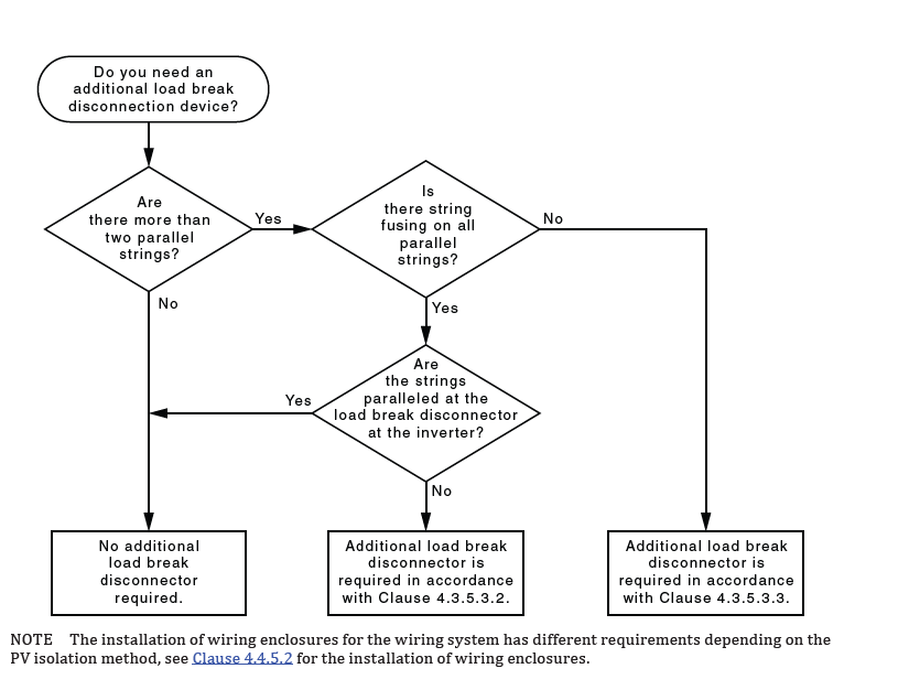
First of all the easy one to assess, 2 strings in parallel or less, no RTI required.
3 or more strings? As long as your string protection is located at the load break disconnector located at the inverter, no RTI required. This means rooftop combiner boxes are going to be out the door as the additional cost of putting a DC isolator inside the rooftop combiner is likely not going to be worth it, this also means inline string fusing (located under the array) and parallel connections at the rooftop become the more expensive option as you will then require RTI’s.
To avoid installing RTI’s every string should get it’s own return cable to the string protection box located at the inverter. This has always been best practice as it makes testing and maintenance a lot easier and it now appears to be the most cost effective option as well. Inverters with string protection built in (Fronius ECO for example) comply with this requirement without doing anything different to how you would be installing them now where you are using the internal string protection.
What are they replaced with?
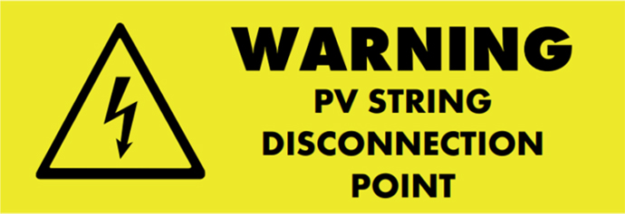
With the abolishment of RTI’s you are instead required to provide a “Disconnection Point”. A disconnection point is going to be a set of MC4’s. 5033:2021 states the disconnection point must
(a) Be adjacent to the PV modules of the PV array.
(b) Be readily available.
(c) Be protected against weather and water, and no more than 150mm from the edge of the PV modules that they are installed under.
NOTE 1 Protection against weather and water could be met by installing the disconnection point under a PV module or by means equivalent to Clause 4.4.7.3.
(d) Adequately supported so that there is no undue stress on the connection, but able to be disconnected.
(e) Have both the positive and negative disconnection device located together.
(f) Labelled in accordance with Clause 5.5.2.2.
(g) Documented in accordance with Clause 5.6
The easiest way to satisfy the new requirements is going to be to bring your array return cables up through the rooftop with enough length to reach an accessible edge of the array. Whack the new label over the end of the cable and terminate some MC4’s on the end.

Once you have installed all your panels, you can connect the string to your disconnection point and clip it to the outside edge of a panel at the end of the array. Finally stick your new label on the panel frame to indicate the location of the disconnection point.
What other situation might you need an RTI?
There is one other situation where you may still need to install an RTI. 5033:2021 introduces new requirements around how you can install DC cabling/conduit within a roof cavity. Where you cannot satisfy the new cable installation requirements you will need to install an RTI to remain compliant.
DC Cabling and Conduit installation requirements
5033:2021 introduces new restrictions around where you can and cannot install DC cabling and conduit. The primary change is that you shall not install DC cabling within 600mm of the ceiling except within certain zones.
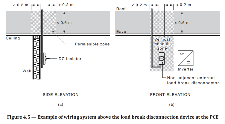
You may install within 600mm of the ceiling within 200mm in a vertical plane of a DC isolator on an internal wall. This allows you to install an inverter on an internal wall as long as your DC conduit goes straight up adjacent to the inverter isolator, and goes straight up and out of the 600mm exclusion zone before changing direction.
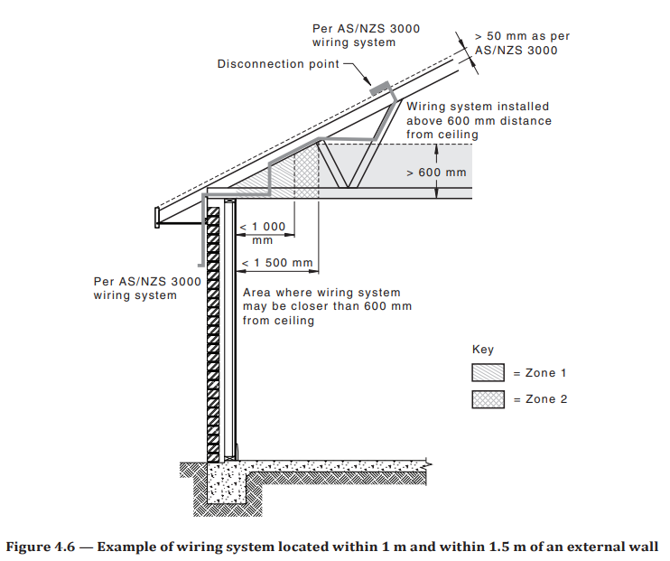
You may install within 600m of the ceiling within 1000mm to 1500mm of the internal surface of an external wall as long as the conduit is clipped to the roof structure.
You may install within 600mm of the ceiling within 1000mm of the internal surface of an external wall with loose conduit (corrugated).
If you cannot satisfy those requirements you may install within 600mm of the ceiling by installing an RTI. This may be necessary in a house where there is a central box gutter you need to run cabling under or some other sort of roof layout where you cannot keep your cabling 600mm off the ceiling. Another situation may be a flat roof with less than 600mm of cavity and the customer does not want surface mount conduit or cable tray on the rooftop and you need to run your DC cabling inside the roof cavity.
Finally, it is important to note that you cannot clip your conduit within 50mm of the roofing material. So keep your conduits high, but not so high they’re touching the roof sheet.
4.4.5.2.3 Wiring systems between disconnection point and load break disconnection device or an application circuit
Wiring systems installed within a ceiling space shall not be located within 0.6 m above the surface of the ceiling unless—
(a) the wiring system is located within 1 m from the internal surface of the external wall, see Zone 1 in Figure 4.6;
(b) the wiring system is located within 1 m to 1.5 m from the internal surface of an external wall, and it is attached to roof structure, see Zone 2 in Figure 4.6; or
(c) the wiring system is located within a vertical plane that extends 0.2 m from the external edge of the load break disconnection device at the PCE or the application circuit, see vertical conduit zone in Figure 4.5.
Where the ceiling space is not greater than 0.6 m in height wiring systems shall not be in the ceiling space unless the wiring system is located within 1 m from the internal surface of the external wall, see Figure 4.6.
NOTE 1 To install a wiring system within a ceiling space that is not greater than 0.6 m in height, a PV isolation method that uses a load break disconnection device may be used.
NOTE 2 These requirements are to prevent the cables from collapsing below the ceiling in the event of a ceiling collapse.
Segregation
Segregation between DC and other cabling was always contentious given AS3000 3.9.8.3 left wriggle room to install different voltage within the same enclosure as long as the requirements of 3.9.8.3 were met. I personally had installed AC and DC cabling within the same cable trays within 50mm in the past given all the cabling was double insulated and rated to the highest voltage present. This is no longer allowed. Segregation from other cabling is specifically called out in 5033:2021. While it is not entirely clear, I do not believe this applies to earth cable which can still be installed in the same conduit as the DC cabling.
4.4.3.2 Segregation
Where PV d.c. circuits are installed near other non PV d.c. cables, they shall be effectively segregated from each other. Effective segregation can be achieved by separation of 50 mm or greater.
Where PV d.c. circuits are installed within 50 mm of other non PV d.c. cables, at least one cable shall be segregated by a medium duty insulating wiring enclosure.
Fireproofing of DC isolators
Where an inverter does not contain a compliant DC isolator and you are required to install a DC isolator adjacent to the inverter it must now be protected against the spread of fire. This can be satisfied by 2 methods.
- Installing an enclosure that is made of metal of at least 0.2mm thickness
- Install a non combustible material that extends 200mm beyond the sides of the DC isolator. Cement sheet would be the likely solution.
You do not have to provide fire protection if the DC isolator is installed on a non combustible surface, Brick or masonry, Concrete, Cement sheeting, Terracotta tile or a metallic surface 0.2mm thick.
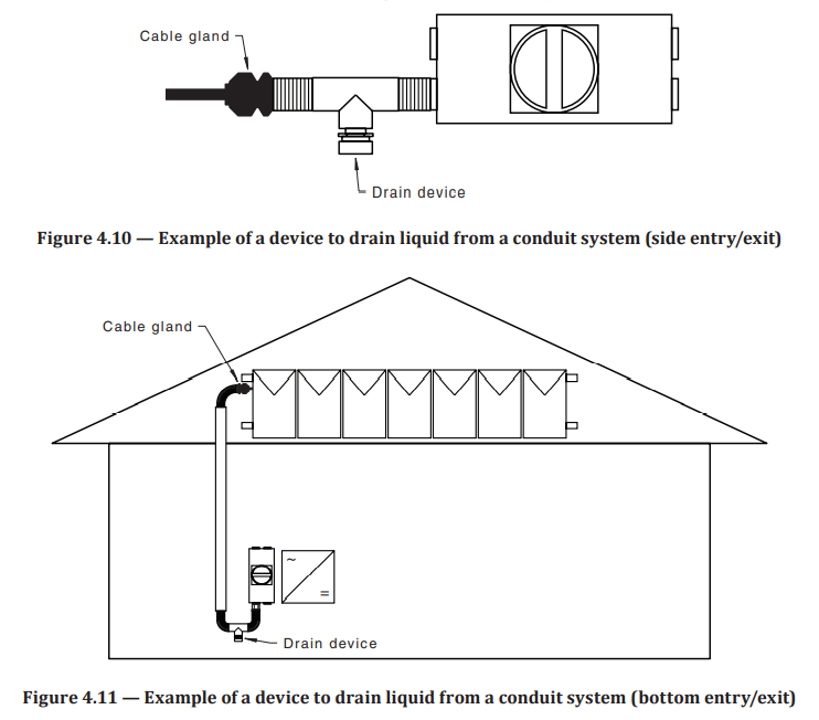
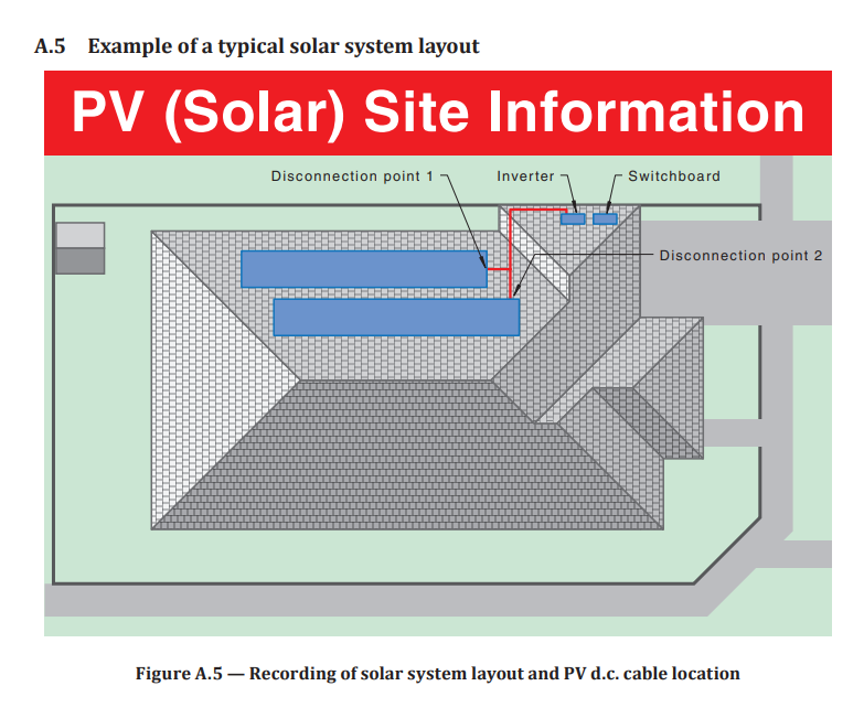
Drain Devices on conduits
It is now a requirement that any continuous conduit system that has any section of it outdoors and terminates into a disconnection device must have a “drain device” fitted at the lowest point of the conduit. This means any conduit terminating into a DC isolator or into an inverter in the case of inverter where you can fit a conduit adaptor and terminate your DC cable internally. The pressure equalisation valve built into most DC isolators now does NOT count as a drain device. In order to avoid this requirement you could use a gland on the enclosure or inverter and have the conduit end before the enclosure. You are still allowed 300mm of exposed cable and this could be used as a gap to prevent water ingress. It is a far less aesthetically pleasing option though.
EXAMPLE OF OPEN ENDED CONDUITS NOT FINISHING IN AN ENCLOSURE
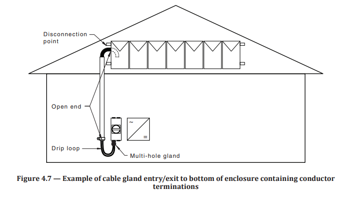
EXAMPLE OF CONDUIT FINISHING IN AN ENCLOSURE WITH A DRAIN DEVICE
Labelling
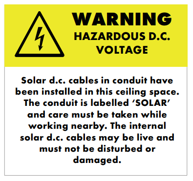
Naturally a solar standard wouldn’t be complete without some ridiculous labelling requirements. While 5033:2021 does reduce the number of labels required. It puts the bulk of the information on to a site plan which must be laminated or behind perspex plastic and located at the MSB or meter position. Exactly how this can be achieved is still up for discussion, Do installers carry a laptop, printer and laminator with them? Maybe a rough sketch on to a template. Given the layout must have white writing on a red background stating “PV (Solar) site information)” this isn’t something you can easily sketch while on site.
5.6 Recording of solar system layout
5.6.1 General
Solar system layout shall be shown on a plan (map or drawing) located at the main switchboard and/or meter box, fire panel. The site information sign shall—
(a) be legible and be sufficiently durable for the location, i.e. be laminated or protected by a solid clear sheet (Perspex, etc);
(b) be fixed permanently in a manner appropriate for the location;
(c) be in English;
(d) be labelled “PV (Solar) site information” in white letters with a red background;
(e) show the location address as recorded for the installation;
(f) contain a plan view of the building showing the location of the PCE, the PV array(s);
NOTE 1 An elevation plan view of the building may also be included for more complex installations. (g) contain a legend for the map or clearly label to identify key components and building reference points;
(h) identify the location of the site information sign with the words “you are here”;
(i) be as accurate as practicable ensuring the various components on the drawing are indicative of the actual installation; and
(j) installation date NOTE 2 See Figure A.5 for example. NOTE 3 In addition to the requirements of this Clause, electronic links such as QR codes may be added to provide additional information
5.6.1.1 Additional information for PV d.c. systems Additional site information for PV d.c. systems shall include:
(a) the path of the d.c. cabling;
(b) the location of d.c. disconnection point(s) indicated by “DP”;
(c) the location of additional load break disconnector(s);
(d) PV array size;
(e) d.c. Voltage; and
(f) contain a warning where d.c. disconnection type(s) can only be operated by suitable qualified personnel.
Labelling (Continued)
The other change to labelling is in regards to the green “PV” label you would have been installing on all jobs. It now must state the type of disconnection point provide (load break or disconnection point) or note that it is an AC system (micro inverters)
5.4 Fire and emergency information
PV systems shall have a circular green reflector sign at least 100 mm in diameter with the letters “PV” on or immediately adjacent to the main metering panel and main switchboard, to be readily visible to approaching emergency workers. Below the “PV” lettering shall include the following:
(a) “AC ” – For inverters where the calculated PV d.c. circuit maximum voltage is less than 120 V d.c. at the inverter PV input, and the PV modules are within 1.5m of the inverter are installed.
(b) “DP” – Where a disconnection point is used as the isolation method.
(c) “SW” – Where a load break disconnection device is used as the isolation method.

Labelling at the manhole
Where DC cabling is installed in a roof space or in an accessible floor space you must install a label adjacent to the access point stating
WARNING: HAZARDOUS d.c. VOLTAGE
Solar d.c. cables in conduit have been installed in this ceiling space. The conduit is labelled ‘SOLAR’ and care must be taken while working nearby. The internal solar d.c. cables may be live and must not be disturbed or damaged
Essentially this means that the label will need to be installed in the roof space or floor space and visible as you enter the cavity. Stick it on the nearest truss or beam or next to the light switch where there is one.
Conclusion
While this analysis isn’t exhaustive and I encourage all installers to read through the new standard themselves, these were the sections I thought were most important for all Solar PV installers in Australia to be aware of immediately.
Do you agree with my analysis? Disagree? Something else you think needs to be brought to attention?
Drop me a line.